Bridge Rectifier Circuit Diagram
How to make bridge rectifier circuit diagram Rectifier bridge diagram make circuit Bridge rectifier circuit diagram with filter
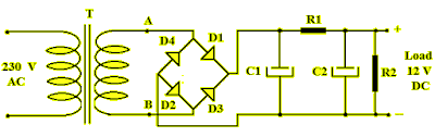
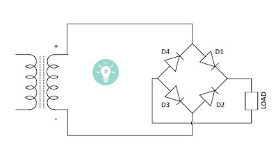
Simple Bridge Rectifier Circuit
Bridge rectifier question. Half bridge rectifier circuit diagram Full wave bridge rectifier circuit working and applications
Bridge rectifier: functions, circuits and applications
Rectifier diodes conductRectifier regulator wiring Bridge rectifierCircuit rectifier bridge diagram simple type.
Rectifier circuit bridge wave figurePower supply circuit diagram using bridge rectifier Simple bridge rectifier circuitRectifier schematic electronics.

69 figure 1.69 shows the circuit diagram of bridge rectifier circuit
Full-wave rectifier circuitRectifier circuit bridge working diagram operation theory ac supply 12v circuits transformer electrical types step down use Rectifier bridge circuit half diagram phase voltage pulse output diode six rectification angle firing motor vs wave dc current diodesBridge rectifier.
Rectifier bridge circuit application applications basics diagram output waveform circuits diodes used diode functions voltage dc power transformer resultant highBridge rectifier diagram circuit working advantages Rectifier bridge circuit simple circuitsBridge rectifier circuit.

Full wave rectifier-bridge rectifier-circuit diagram with design & theory
Circuit rectifier charger fritzing schematic breadboard geek rectifiersFull-bridge rectifier circuit diagram Rectifier diode capacitor diodes circuitdigestRectifier circuit diagram wave output waveform input.
Diagram rectifier bridge wiring circuit wave applicationsRectifier circuit diagram Bridge rectifier: functions, circuits and applicationsRectifier circuit schematic.
Bridge rectifier-working diagram advantages
Rectifier circuit bridge diagram wave working detailsSimple bridge rectifier circuit Simple bridge rectifier circuit diagramBridge rectifier : circuit diagram, types, working & its applications.
Rectifier transformer wiring consists diode resistor diodesBridge rectifier – national circuits Rectifier circuit bridge simple diagram ac transformer tapped providing voltage using centerFull wave bridge rectifier circuit.

Rectifier cycle capacitor
13+ bridge rectifier schematicRectifier bridge circuit applications circuits functions d3 d1 conduction u2 d4 d2 path stop current .
.


